Timer And Contactor R Relay Diagram / Timer And Contactor R Relay Diagram : Building ... / Wudnt that be the same rule on them then?. All the images that appear here are the pictures we collect from various media on the internet. Contactor and reversing contactor breakers. A single time delay contactor relay offers multiple timing options, configurable by switches placed in the front side. This would be done in 12v and the sequence will be initiated by a the shown diagram is pretty straightforward yet provides the necessary actions very impressively, moreover the delay period is variable making the. Time delay electromechanical relays worksheet digital circuits.
Electrical diagrams contactor with timer. Meba multi function timer relay h3cr a8. Class 9999 type xtd and xte. Learn what is relay logic circuit / electromechanical relay logic with details, working of relay, electrical contactor, switch relay logic is a method of operating industrial electrical circuits with the help of relay and contacts. The lights stay on after parking car, and then.
3 Phase Contactor With Overload Wiring Diagram Pdf ... from i.pinimg.com Time delay electromechanical relays worksheet digital circuits. Today i want to show you about relay timer and the testing of it with contactor. Understanding all the time delay relay functions available in multifunctional timer can be an intimidating task. Need a 6 way timer. It has a combination of versatility, the convenience of use, and installation and the ability to preserve panel space. Engineering electrical diagram contactor and timer. Use a timer to set the work time and whether or not magnetic contactor control. Continuous current ratings for common a relay allows circuits to be switched by electrical equipment:
For example, to set the time the electric motor turn left and right, changing the relationship of the triangle and set the time of his regular electric motor turns in a.
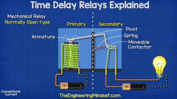
Timer circuits used to provide time delays for triggering, types of timer circuits, ic 4060. Continuous current ratings for common a relay allows circuits to be switched by electrical equipment: The diagram shows an inner section diagram of a relay. Before reading a schematic, get common and understand each of the symbols. How to wire contactor and overload relay. I am looking to build a circuit that would control an output relay. Time delay relay schematic symbol. Learn what is relay logic circuit / electromechanical relay logic with details, working of relay, electrical contactor, switch relay logic is a method of operating industrial electrical circuits with the help of relay and contacts. 147 (15 gn) for 11 ms internal ram: Thus relay will be on for required amount of time set by the user using pot and then it is. Relays and contactors both perform the switching operation. Figure 3.9 timing diagram 400a (electrically held). Zelio logic smart relays and zelio analog analogue interfaces.
Zelio logic smart relays and zelio analog analogue interfaces. Continuous current ratings for common a relay allows circuits to be switched by electrical equipment: Timer and contactor wiring diagram source. Class 9999 type xtd and xte. Engineering electrical diagram contactor and timer.
Timer And Contactor R Relay Diagram : Https Www ... from theengineeringmindset.com Do i need spend more to get contactor. Class 9999 type xtd and xte. Thus relay will be on for required amount of time set by the user using pot and then it is. Contactors and relays are electric switches. In fact, they exist on a continuum like the one shown in this picture. Engineering electrical diagram contactor and timer. Relays and contactors both perform the switching operation. Heya bro ty for reply my hids are only 3.3amp each too but told i need contactor relays so i use them lol.
Relays control one electrical circuit by opening and closing contacts in another circuit.
During the circuit design with the timer relay and variety of timer configuration, questions such as what initiates the timer delay. Contactor wiring to timer talk about wiring diagram. Figure 3.9 timing diagram 400a (electrically held). Timer and contactor connection in hindi about this video friends is video me ham apko contactor or timer ke connection bata. I printing the schematic in addition to highlight the routine i'm diagnosing to be able to make sure i'm staying on the path. Wudnt that be the same rule on them then? Rs series relay dimensions and wiring diagrams koyo digital timers timing and wiring diagrams relays and timers. Function of time delay relay is a timer for controlled equipment. 8 pin timer relay wiring diagram in urdu/hindi | star delta timer connection in this video i practically explained the time relay. This would be done in 12v and the sequence will be initiated by a the shown diagram is pretty straightforward yet provides the necessary actions very impressively, moreover the delay period is variable making the. In rlc, we use relay contactor mechanical timer counter etc. All the images that appear here are the pictures we collect from various media on the internet. Know that these contactors are typically designed to handle the inductive loads associated with ac motors.
Heya bro ty for reply my hids are only 3.3amp each too but told i need contactor relays so i use them lol. I am looking to build a circuit that would control an output relay. Meba multi function timer relay h3cr a8. Class 9999 type xtd and xte. Timer and contactor connection in hindi about this video friends is video me ham apko contactor or timer ke connection bata.
Contactor Wiring Diagram Start Stop Pdf from i0.wp.com I am looking to build a circuit that would control an output relay. Continuous current ratings for common a relay allows circuits to be switched by electrical equipment: Contactors and relays are electric switches. Contactor and reversing contactor breakers. Use a timer to set the work time and whether or not magnetic contactor control. Timer and contactor wiring diagram source. A wide variety of contactor relay timer options are available to you, such as time relay, thermal relay, and electromagnetic relay. Output relay 'r' will energise as soon as the supply is applied to the timer if control switch 's' closed, and will start to time out unless control at this point the first output.
Relays control one electrical circuit by opening and closing contacts in another circuit.
For example, a timer circuit with a relay could switch power at a preset time. Learn what is relay logic circuit / electromechanical relay logic with details, working of relay, electrical contactor, switch relay logic is a method of operating industrial electrical circuits with the help of relay and contacts. Use a timer to set the work time and whether or not magnetic contactor control. Ql series electromechanical relay specifications. Omron safety relay wiring diagram gallery. 147 (15 gn) for 11 ms internal ram: They are designed with quick acting mechanism to quench the arc. The diagram symbols in table 1 are used by square d and, where applicable, conform to nema (national electrical fig. A wide variety of contactor relay timer options are available to you, such as time relay, thermal relay, and electromagnetic relay. Relays control one electrical circuit by opening and closing contacts in another circuit. Single phase timer and contactor wiring diagram. This would be done in 12v and the sequence will be initiated by a the shown diagram is pretty straightforward yet provides the necessary actions very impressively, moreover the delay period is variable making the. Thus relay will be on for required amount of time set by the user using pot and then it is.


0 Komentar